

Integrating 35kV switchgear into a centralized monitoring system (such as SCADA or EMS) is a critical step for modern substations, renewable energy plants, and heavy industrial power grids. A robust monitoring setup provides real-time visibility into temperature, insulation integrity, and breaker status-preventing catastrophic failures and optimizing maintenance schedules.
However, operating at 35kV (often specified up to a 40.5kV maximum rating) introduces strict safety requirements and severe electromagnetic interference (EMI). Below is a professional engineering guide on how to successfully connect 35kV switchgear to your monitoring system.

Step 1: Architect the Communication & Hardware Topology
Unlike low-voltage systems, a 35kV monitoring system relies on a three-tier architecture: Bay Level (Sensors) ➔ Unit Level (IEDs/Protection Relays) ➔ Station Level (SCADA/HMI).
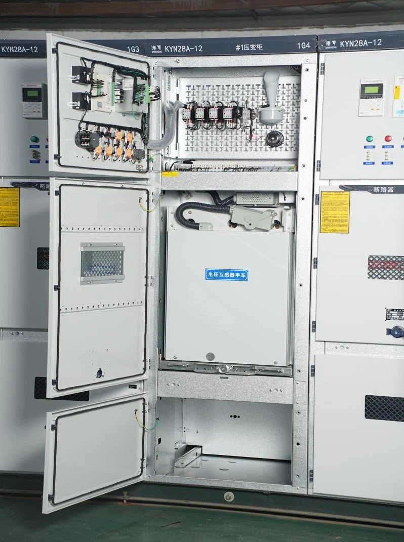
Before installation, you must ensure your monitoring system supports the specific hardware interfaces of your switchgear. For example, high-quality 35kV cabinets like Hongheng's KYN61-40.5 Removable AC Metal-Enclosed Switchgear and XGN17-40.5 Fixed Switchgear are engineered with dedicated low-voltage compartments to house these intelligent components safely away from the high-voltage busbars.
Step 2: Deploy Specialized MV Sensors
Standard sensors cannot survive the high-voltage environment of a 35kV system. You must deploy specialized, isolated monitoring devices:
Wireless Temperature Sensors: Installed directly onto critical contact points like busbar joints, cable terminations, and the arm contacts of the Vacuum Circuit Breaker (VCB). These must use wireless RF or passive online surface acoustic wave (SAW) technology to ensure galvanic isolation.
Partial Discharge (PD) Sensors: Ultra-High Frequency (UHF) or Transient Earth Voltage (TEV) sensors are mounted inside the cable and breaker compartments to monitor insulation degradation before a flashover occurs.
Current & Voltage Transformers (CTs/PTs): Utilize secondary outputs (typically 5A/1A or 100V) to feed analog data safely into the monitoring modules.
Step 3: Implement Intelligent Electronic Devices (IEDs) & Relays
The analog and wireless signals from the sensors cannot connect directly to a computer. They must be aggregated by Intelligent Electronic Devices (IEDs) or advanced Microcomputer Protection Relays installed in the low-voltage compartment of each 35kV panel.
Data Aggregation: The IED converts raw sensor data (temperatures, binary contact statuses, coil currents) into digitized data packets.
Local Control Interlocking: The relay ensures that local electrical control and remote commands conform to pre-defined safety logics (e.g., preventing the grounding switch from closing while the circuit breaker is racked in).
Step 4: Establish Protocol Communication (IEC 61850 Compliance)
To transmit data from the switchgear room to the central control room, you must configure the communication protocol.
[35kV Switchgear Sensors] ──> [Local IED / Relay] ──(IEC 61850 over Fiber Optic)──> [Central SCADA]
Protocol & Media Standards for 35kV Systems
The Industry Standard: IEC 61850 is the global standard for substation automation. It enables high-speed, interoperable communication between different manufacturers' equipment via GOOSE and SV messaging.
Alternative Legacy Protocols: Modbus RTU (over RS485) or DNP3 can be used for simpler setups but lack the speed and data depth of IEC 61850.
The Transmission Medium: Fiber Optic Cables are mandatory for the communication backbone. High-voltage 35kV switching generates immense electromagnetic pulses (EMP) that will corrupt data on traditional copper Ethernet cables and potentially damage network switches.
Step 5: Configure Thresholds, Testing, and Commissioning
Once the physical and digital networks are linked, the system must undergo rigorous commissioning:
Alarm Threshold Mapping: Define multi-stage alerts within the SCADA software. For instance, set a Warning at a busbar temperature of 75°C and a Critical Trip Trigger at 90°C.
Signal End-to-End Testing: Manually actuate auxiliary contacts and inject simulated currents to verify that the central monitoring system correctly displays breaker positions (Open/Closed/Tripped) and accurate electrical values.
Interference Testing: Perform test operations on the 35kV vacuum circuit breaker under safe conditions to ensure that the communication link does not drop or glitch during a live switching arc.
Mitigating Key Challenges in 35kV Monitoring
Electromagnetic Interference (EMI): Always separate low-voltage control routing from 35kV power cables. Ensure the switchgear cabinet frame and sensor shielding are bound to a unified, low-resistance substation grounding grid.
Sensor Longevity: The harsh thermal and ozone environment inside an MV cabinet accelerates component aging. Choose sensors with a high IP rating (IP65 or higher for enclosed sensors) and high-temperature tolerance.
Conclusion
Connecting a 35kV switchgear to a monitoring system requires a deep understanding of high-voltage isolation, digital communication protocols like IEC 61850, and EMI mitigation.
As a premier manufacturer of medium-voltage power solutions, Hongheng (ghswitchcabinet.com) provides fully integrated 35kV/40.5kV switchgear solutions equipped with pre-engineered smart sensor arrays, premium protection relays, and fiber-optic communication ports ready for seamless SCADA integration.
Contact our engineering division today to get technical blueprints, customized control schemes, or a direct B2B factory quote for your substation project.
References
IEC 62271-200: High-voltage switchgear and controlgear – Part 200: AC metal-enclosed switchgear and controlgear for rated voltages above 1 kV and up to and including 52 kV.
IEC 61850: Communication networks and systems for power utility automation.
IEEE Guide for Safety in AC Substation Grounding (IEEE Std 80).