

GGD Low Voltage Fixed Complete Switchgear - Circuit Scheme Selection Guide
GangHeng's GGD switchgear is designed for power plants, substations, industrial and mining enterprises, and high-rise buildings, operating on 50Hz, 380V AC systems with rated currents up to 3150A. It is used for power conversion, distribution, and control of motor, lighting, and general distribution equipment. This guide helps you quickly identify the right configuration based on your transformer capacity and cabinet role (incoming, feeder, or bus-tie). Beyond the standard scheme library, GangHeng also offers custom configurations at the same price as standard products.
Complies with GB7251 Low-Voltage Switchgear and Controlgear Assemblies and JB/T5877 Low-Voltage Fixed Enclosed Switchgear and Controlgear Assemblies.
1. How to Select
-
Step 1 - Determine the Cabinet's Functional Role

Role Description Incoming Cabinet Overhead or cable incoming, bringing utility/transformer power into the distribution system Feeder Cabinet Distributes power to downstream loads - covers standard outgoing feeders, motor-dedicated feeders, lighting circuits, and reactive power compensation Bus-tie Cabinet Dual-power switching or bus-section tie-in, improving supply reliability These three roles can be configured individually or combined (e.g., Incoming + Bus-tie, Bus-tie + Feeder + Standby).
-

Step 2 - Determine Cabinet Type and Current Rating Based on Transformer Capacity
Cabinet Type Rated Current Steps Rated Breaking Capacity Rated Short-Time Withstand Rated Peak Withstand GGD1 A: 1000A / B: 600(630)A / C: 400A 15kA 15kA/1s 30kA GGD2 A: 1500(1600)A / B: 1000A 30kA 30kA/1s 63kA GGD3 A: 3150A / B: 2500A / C: 2000A 50kA 50kA/1s 105kA The exact current rating should be confirmed by an engineer based on actual transformer capacity and load calculations. If you can provide your transformer capacity, our engineering team will match the precise cabinet type and current step for you.
-
Step 3 - Review Reference Schemes Under the Matching Category
Each cabinet role (Incoming / Feeder / Bus-tie) has multiple standard circuit schemes available - see the categorized library below, or consult the full scheme library for the complete set.
2. Circuit Scheme Library by Function
Category 1: Incoming Cabinet
Brings power into the distribution system via overhead or cable incoming lines. Can be configured standalone, or combined with bus-tie or standby functions (e.g., "Incoming + Bus-tie", "Incoming + Standby") for dual-power supply or main/backup switching. Key components include circuit breakers (frame-type or molded-case, manual or motor-operated) and current transformers.


Category 2: Feeder / Outgoing Cabinet
Distributes power to downstream loads. This is the most diverse category, covering: standard multi-way outgoing feeders, motor-dedicated feeders (with thermal relay overload protection), lighting circuit feeders, and reactive power compensation (capacitor banks). Outgoing feeders are typically fitted with current transformers for metering and protection; the number of ways and breaker ratings are configured flexibly based on load requirements.

Scheme 31–36 | Standard Multi-Way Feeder | Width 600–800mm, Depth 600mm | For distributing power to multiple downstream loads

Scheme 55–60 | Motor-Dedicated Feeder | Width 800mm, Depth 600mm | Fitted with thermal relay protection, for pump rooms, fans, and other motor loads

Scheme GGJ1-01 (Main) / GGJ1-02 (Auxiliary) | Reactive Power Compensation | Width 800–1000mm, Depth 600mm | Power factor correction, configurable as main or auxiliary cabinet
Category 3: Bus-tie Cabinet
Used for bus-section tie-in or dual-power switching. Can be configured standalone, or combined with feeder or standby functions (e.g., "Bus-tie + Feeder", "Bus-tie + Feeder + Standby") to improve system reliability - commonly used where dual power sources or bus-sectioning are required.


The schemes above are representative examples. The full GGD1/GGD2/GGD3 series includes 60+ standard circuit schemes. [View Full Scheme Library →]
Structural Features
General-purpose cabinet frame, welded and assembled from 8MF cold-formed steel, with 20-module mounting holes for high interchangeability
Ventilation slots at top and bottom form a natural convection cooling path
Golden-ratio proportions for a clean, modern appearance
Door edges fitted with mountain-profile rubber seals; hinge-chain connection for easy installation and removal
Instrument doors grounded via multi-strand flexible copper cable, forming a complete protective earthing circuit
Polyester orange-peel powder coating, strong adhesion, matte finish
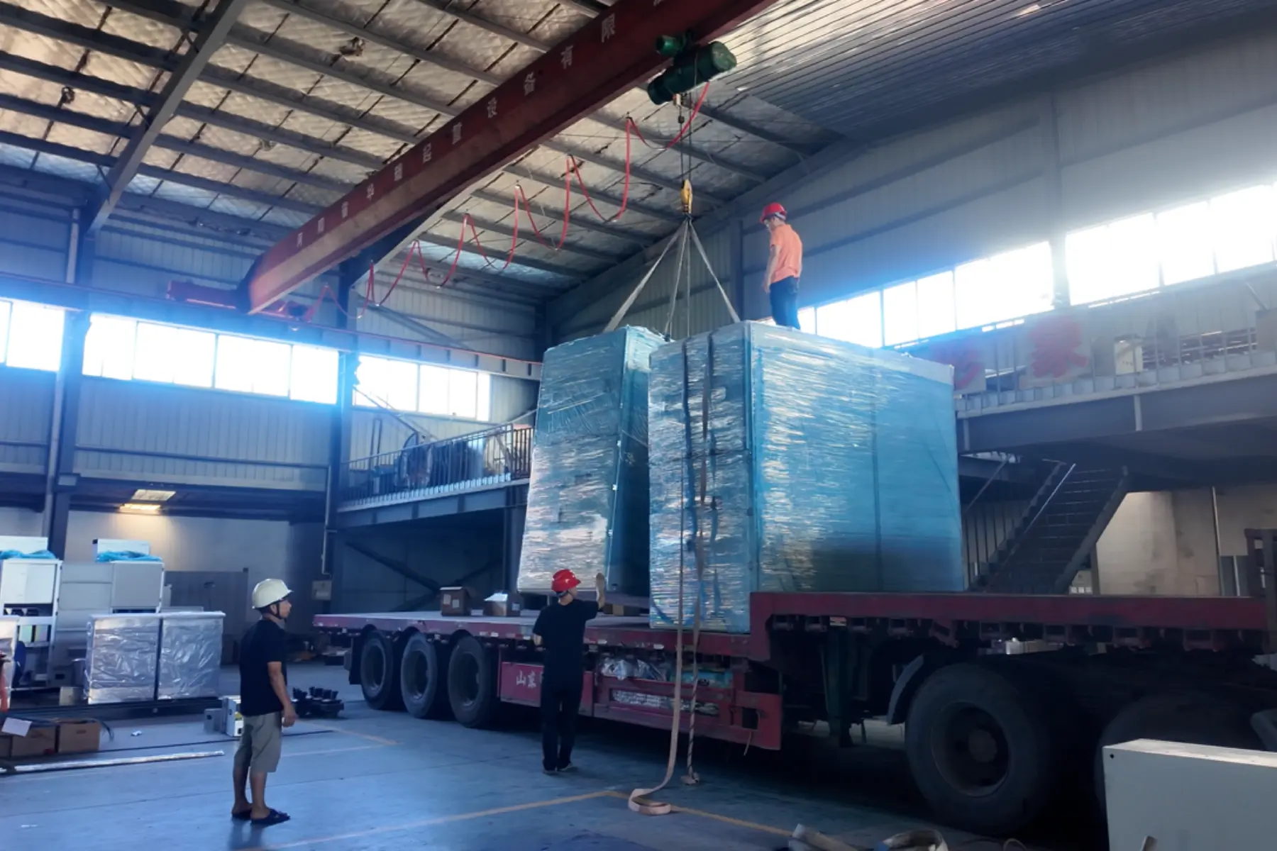
Removable top cover; lifting rings at all four corners for easy handling and transport
Standard protection rating IP30, adjustable between IP20–IP40 per site requirements
Operating Conditions
Ambient air temperature: -5°C to +40°C, 24-hour average not exceeding +35°C
Indoor installation; altitude not exceeding 2000m
Relative humidity: not exceeding 50% at +40°C; higher humidity permitted at lower temperatures (e.g., 90% at 20°C) - condensation risk from temperature changes should be considered
Installation tilt not to exceed 5° from vertical
Should be installed in locations free from severe vibration, shock, or corrosive conditions
Special requirements can be discussed with GangHeng's engineering team

Custom Circuit Scheme Configuration
Beyond the standard scheme library, GHS offers custom GGD circuit configurations:

Path A - With Technical Parameters
Customer provides transformer capacity, system drawings, and other parameters; GHS's engineering team delivers a custom scheme directly.
Path B - Without Technical Parameters
Customer provides site information, on-site equipment power ratings (e.g., machinery load data), and desired functional outcomes; GHS's engineering team derives and delivers a custom scheme accordingly.

Notes:
- Custom configurations are priced the same as standard schemes
- Cabinet dimensions may be widened depending on the specific configuration
- No minimum order quantity
- GHS brings 23 years of industry experience, is a qualified supplier for State Grid and China Southern Power Grid, and holds ISO9001 and CCC certifications
Ordering Information
When placing an order, customers should provide:
- Full product model number
- Main circuit system arrangement diagram
- Auxiliary circuit schematic diagram
- Bill of materials for in-cabinet components
- Any special requirements outside standard operating conditions
If this technical documentation is not available, please refer to Custom Path B above - GangHeng's engineering team will assist in developing the scheme.
Frequently Asked Questions
Q: What are incoming, feeder, and bus-tie cabinets used for?
Incoming cabinets bring power (utility or transformer) into the distribution system. Feeder cabinets distribute power to downstream loads, covering standard outgoing feeders, motor feeders, lighting, and reactive power compensation. Bus-tie cabinets handle dual-power switching or bus-sectioning to improve reliability. All three can be used standalone or combined.
Q: How do I know whether to choose GGD1, GGD2, or GGD3?
This is primarily determined by transformer capacity/system rated current: GGD1 covers 400–1000A, GGD2 covers 1000–1600A, and GGD3 covers 2000–3150A. We recommend providing your transformer capacity so our engineers can confirm the exact match.
Q: What if I don't have transformer parameters?
You can provide site information, on-site equipment power ratings, and your desired distribution function - GHS's engineering team will help derive a suitable custom scheme.
Q: Why do outgoing feeder cabinets need current transformers?
Current transformers are used for accurate metering and protection, ensuring reliable monitoring and overload protection on each outgoing circuit.
Q: Does a custom scheme cost more?
No - custom configurations are priced the same as standard schemes. Cabinet dimensions may only be widened where the configuration requires it.
Q: Can the protection rating be customized?
Standard rating is IP30, adjustable between IP20–IP40 based on site environmental requirements.
Q: Where can I see all 60+ standard schemes?
Click "View Full Scheme Library" on this page to access the complete GGD main circuit scheme manual, organized by cabinet type (GGD1/GGD2/GGD3) with all standard scheme numbers and configuration details.
Request a Technical Proposal
Please provide the following information, and GHS's engineering team will match or customize a GGD circuit scheme for you:
If technical parameters are available:
- Transformer capacity
- System voltage level
- Related drawings

If technical parameters are not available:
- Site information
- On-site equipment power ratings
- Desired distribution function